Lesson 7: RECOGNITION OF ROAD BOUNDARIES, ROAD USERS AND OBSTACLES I: USING A CAMERA
In this lesson, we’ll delve into how autonomous vehicles utilize cameras to recognize road boundaries and identify obstacles, such as vehicles, cyclists, and pedestrians.
- Introduction to Camera-Based Recognition
- Cameras play a pivotal role in the perception capabilities of autonomous vehicles.
- They are employed to identify crucial elements on the road, including road boundaries and various obstacles.
- This lesson provides fundamental insights into how camera imagery is processed to create a comprehensive view of the road environment.
- Photogrammetry Basics
- Photogrammetry is the underlying technique used to convert camera images into a coherent representation of the road.
- While we won’t delve deeply into the technical intricacies, we will cover some fundamental photogrammetric concepts.
- Photogrammetry is a key component in the process of recognizing road boundaries and obstacles using cameras.
- Camera Angle and Position
- Understanding the camera’s position and angle is essential for accurate recognition.
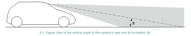
- Figure 1 illustrates the camera’s vertical angle (θ) and its inclination concerning the road’s horizontal plane.
- We assume constant road slope for simplicity but recognize that real-world scenarios may involve varying slopes.
- This foundational assumption aids in later calculations and can be refined to account for changing road slopes.
- Drawing the Road Layout
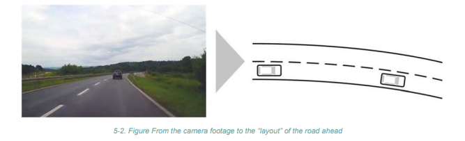
- The primary goal is to create a road layout display with moving and stationary obstacles based on camera input.
- Figure 2 exemplifies this by showing the desired output.
- Photogrammetric principles and equations will be employed to achieve this objective.
- Camera Position in Vehicle Coordinate System
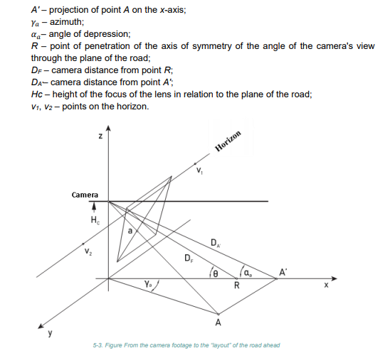
- Figure 3 depicts the camera’s position in relation to the vehicle’s coordinate system.
- Key points to note: point A on the road corresponds to point a in the camera image, and the distance between the lens and the observed objects is significant.
- This distance is equivalent to the focal length multiplied by the positive magnification.
- Point a represents the position in the photograph of point A located on the road in front of the vehicle, with the following markings:
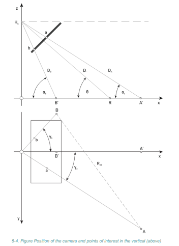
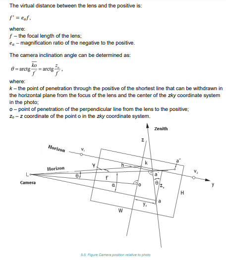
- Camera Position in Vertical and Horizontal Plane
- Figure 4 shows the position of the camera in the vertical and horizontal plane, but also the position of points of interest.
- Figure 5 illustrates the camera’s position concerning the photograph’s dimensions (width W and height H).
- Point a on the photo corresponds to point A on the road.
- These insights help calculate key parameters such as azimuth, angle of depression, and distances between points.
- Deriving Equations for Calculation
- Equations for various parameters will be derived to enable precise calculations, including:
- Azimuth of a point
- Angle of depression
- Coordinate x of point R
- Distances between points
- Distance between points A and B
- These calculations are instrumental in creating an accurate road layout.
- Obtaining the Road Layout
- With the position of all relevant points and their mutual distances calculated as demonstrated, the vehicle’s control unit can construct the desired road layout.
- This layout provides a clear picture of the road ahead, aiding in decision-making for the autonomous vehicle.
Conclusion
- Camera-based recognition of road boundaries, road users, and obstacles is a vital component of autonomous vehicle perception.
- Understanding the principles of photogrammetry and camera positioning is essential for developing robust autonomous driving systems.
- In the next lesson, we will explore the role of artificial neural networks in recognizing road features and objects based on camera data.