Lesson 7: Stress theories
In this lesson, we will delve into various theories that help us understand how materials respond to stress and predict failure. Understanding these theories is essential in engineering and material science.
1 MULTIDIRECTIONAL COMPLEX LOADS
- Simultaneous tensile-compressive (σ) and shear (𝜏) stresses
- Bending + shearing
- Bending + torsion
- Tension-compression + torsion
- Tension-compression + shearing
- Bending + shearing + tension
- Bending + shearing + torsion
- Bending + tension + torsion
- Tension + torsion + shearing
- Bending + tension + shearing + torsion
- Superposition does not work. Reduced stress is required
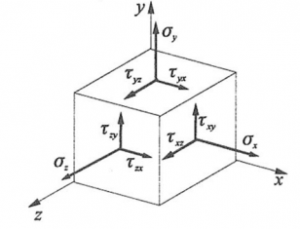
- Spatial stress state:
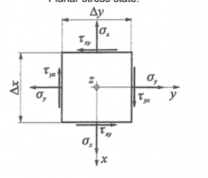
- Planar stress state:
2 COULOMB’S THEORY
- Failure occurs at a point in the material when the maximum normal stress at that point reaches the tensile or compressive failure strength.
![]()
- According to Coulomb, the reduced stress is equal to the highest absolute value of the principal stresses.
- For brittle materials, Coulomb’s theory gives a good description of failure when there is a dominant principal stress, compared to which the other two principal stresses are less dangerous.
3 HUBER – VON MISES – HENCKY (HMH) THEORY
- Two stress states are equally dangerous to failure if their deformation energies are equal.
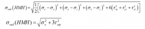
- The HMH theory gives a good description of the occurrence of failure for ductile materials.
4 MOHR’S THEORY
- Two general spatial stress states are equally dangerous for failure if the diameters of their corresponding maximum Mohr circles are equal.
- According to Mohr, a stress state in a point is characterised by the diameter of the largest Mohr circle for damage.
- Mohr’s theory gives a good prediction of the occurrence of failure for ductile materials.
- The reduced stress calculated by Mohr and HMH theory differ only slightly.
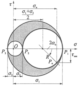
5 PLANAR PRINCIPAL STRESS
MOHR’S PLANAR STRESS CIRCLE DIAGRAM DRAWING PROCESS
- Draw a cartesian σ-𝜏 coordinate system.
- Measure σx on the horizontal axis.
- Measure 𝜏xy at σx and 𝜏yx at 0.
- Connect the obtained points, obtain the center and radius of circle 1-2.
- We draw the MOHR circle 1-2.
- If necessary for the calculation, draw circles 1-3 and 2-3.
- Calculate the values of K and R.
- From this we calculate σ1, σ2, and φ.
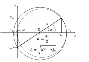
- From these, the equations for the principal stresses can be obtained, but it is best not to use them, the circle is more reliable.
- The sign of 𝜏 is determined in the local right-handed n-m coordinate system.
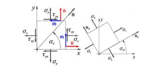
- n is perpendicular to the plane under consideration, and the sign of 𝜏 is shown on m.
- With this method, the sign of 𝜏 can be determined in any position or rotation of the elementary unit.
Understanding stress theories is crucial in designing structures and materials to withstand various loads and prevent failure. These theories provide engineers and scientists with valuable tools for analyzing stress states and ensuring the safety and integrity of materials and structures.