Lesson 3 – Divider Fixture, Tool setting and tool guiding elements….
Read the textbook from the 55th page. You can find the textbooks’s content on this link.
4. DIVIDER FIXTURES
It is often necessary to change the location of a clamped workpiece in relation to the tool without holding the workpiece. The different locations are achieved by means of a dividing device. With regard to the direction of movement, a distinction is made between circular and longitudinal dividers. The latter are only rarely used, so we will briefly discuss only the circular strokers here.
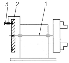
The main parts of a circular divider are as follows (Figure 4-1):
_the dividing shaft (1), which rotates together with the workpiece clamping part,
_dividing plate (2), most often fixed to the shaft,
_latch (3).
Figure 4-1. Main parts of a circular divider
The dividing plate is usually made with bores or grooves corresponding to the number of divisions (Figure 4-2). It is important that the bores (slots) are as far away from the axis of rotation as possible, as this will reduce the division error due to clearance between the slot and the latch.
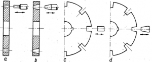
Figure 4-2. Dividing plate and latch designs [9]
a) cylindrical, b) conical, c) slotted, d) wedge
THE FOLLOWING SOLUTIONS CAN BE USED FOR THE LATCH DESIGN:
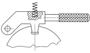 _cylindrical pin (simple to manufacture, it pushes any chips that may have fallen into the slot out of the slot, there is some play between the slot and the latch), _tapered pin (provides a clearance-free fit, with the possibility of shavings being trapped between the slot and the latch) _slotted (rare) and wedge (same characteristics as described for cylindrical and tapered pins), _in the case of a handle latch, the latch does not turn in a straight line, but around a pin (Figure 4-3), _ball latches are simple in design, release with little force and are often used as an auxiliary device to facilitate other latching operations (Figure 4-4).
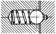
Figure 4-4. Ball latch
If there is some clearance between the latch and the slot, this will lead to vibrations during machining, so the dividing plate must be fixed after dividing. In most cases, this can be achieved by screw or eccentric clamping. Depending on the clamping direction relative to the dividing plate, the clamping can be axial or radial.
Longitudinal dividers can be used for machining bores or grooves spaced apart by a certain distance. The moving part of the device can be moved in a guided manner and the locking is done in the same way as already described.