Lesson 2 – Clamping of workpieces
Read the textbook from the 28th page. You can find the textbooks’s content on this link.
3. CLAMPING OF WORKPIECES
3.1 BASIC CONCEPTS
Workpiece clamping is the act of fixing the workpiece so that it cannot be moved from the seats by chipping and other forces during machining. The elements of the fixture with which the clamping is performed are called clamping elements. A distinction is made between main and assisted clamping (Figure 3-1). The function of the assist clamp is to press the workpiece onto the seats prior to the main clamp. In most cases, it works with an elastic element (spring). They are not necessarily a necessary part of the machine, but their use usually makes workpiece changes faster.
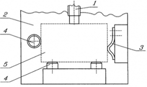
- clamping screw
- fixture body
- flat spring as assist clamp
- seats
- workpiece
Figure 3-1. Assisted clamping with flat spring
3.1.1 POSITIONING OF THE CLAMPING FORCE Based on the line of action of the clamping force, the clamping can be perpendicular to the plane locating surface or parallel to the plane locating surface (lateral clamping). In the case of perpendicular clamping, the clamping surfaces are located on the sides adjacent to the plane locating surface or on the opposite side, while in the case of lateral clamping, the clamping surfaces are always located on the sides adjacent to the overlying surface (Figure 3-2).
Another important characteristic of the clamping is the number of points at which clamping occurs. According to the number of clamping points, a distinction can be made between one, two-, three- and four-point clamping.
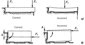
The location of the clamping should be chosen so that the closing force is applied through the plane locating surface. The transfer of force should preferably be through the seats (Figure 3-3).
Perpendicular clamping Parallel clamping
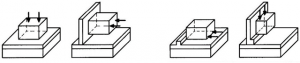 Figure 3-2. Perpendicular and parallel clamping [19]
a) perpendicular clamping b) lateral clamping
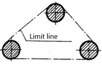
In the case where it is not possible to transfer force through the seats, the clamping force has to be positioned within the plane locating limit line (Figure 3-4).
Figure 3-4. Plane locating limit line
The chipping process and the fixture should preferably be designed in such a way that the applied chipping force is applied to the seat to clamp the workpiece (Figure 3-5).
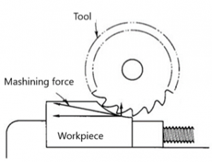
Figure 3-5. Clamping on the seat [11]