Lesson 3 – Milling
Read the textbook from the 63th page. You can find the textbook’s content on this link.
5. MILLING
Milling, cutting with a circular main movement of a multi-edged tool (milling) and an advanced, feed movement of the workpiece. Separation of chips of variable cross-section is intermittent. It is used for the production of planes, grooves, log surfaces, round cylinders, but it is also suitable for creating any surface (profile milling, contour milling). It is a widespread process, as it is suitable for the production of all types of surfaces, from the simplest to the most complex. Its advantageous features are productivity and the relatively high accuracy that can be achieved.
5.1 THE VERSIONS OF MILLING
Milling has a large number of variants, which can be divided according to the shape of the machined surface, the shape of the tool and the kinematic conditions of the machining. An important feature of the cutting process is which part of the tool edge forms the machined surface. Accordingly, a distinction is made between peripheral milling and face milling. In the case of mantle milling, the machined surface is formed only by the main edges located on the milling mantle surface (Figure 5-1). In face milling, chip removal is also done with the main edges on the circumferential surface, but the machined surface is formed by the side edges on the face of the milling machine. There are also boundary cases (shape milling, thread milling, etc.) that can be classified into both groups.
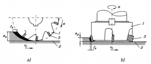
Figure 5-1. Comparison of slab milling and face milling: a) slab milling;
b) face milling;
1- tool, 2- workpiece, 3- cutting edge
Based on the relationship between the feed and the main movement, the milling can be opposite (conventional) or straight (Figure 5-2). In the case of parallel milling, the direction of the circumferential speed of the edges associated with the workpiece and the direction of the side movement are “the same” (they have a component in the same direction). Here, the chip thickness is the largest at the edge. It has a better surface quality than straight milling, and a longer tool life, but can only be used on machines where there is no gap in the kinematic chain of the offset movement.
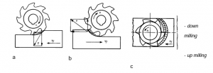
Figure 5-2. Down- and up milling: a) down milling; b) up milling; c) combined milling
In the case of counter-milling, the chip thickness at the edge entry is h=0, so in the initial phase the material is elastically deformed and significant friction occurs on the back surface of the tool. Depending on the relative position of the tool and the workpiece, face milling can also be performed in the opposite direction and in the same direction (combined milling).
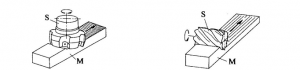
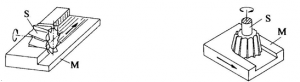
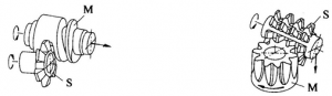
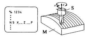
DIN 8589 classifies the milling variants into seven basic variants (Figure 5-3):
(1) face milling with face mill cutter, (2) face milling with slab mill cutter, (3) face milling with shell end mill cutter (angle milling), (4) profile milling, (5) thread milling, (6) hobbing, (7) contour milling (sculpture surface milling).
Face milling with face mill cutter Face milling with slab mill cutter
 Face milling with shell end mill cutter Profile milling
 Thread milling Hobbing
 Contour milling
Figure 5-3. Basic milling variants according to DIN 8589 (M-workpiece, S-tool)