Lesson 2 – Drilling
Read the textbook from the 47th page. You can find the textbook’s content on this link.
2.6. DEFINITION OF THE MACHINE TIME FOR TURNING
Knowing the cutting parameters and the dimensions of the workpiece, the machine main time required for cutting can be determined for each operation: 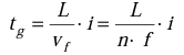
Where:
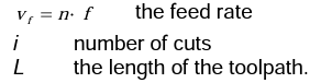
Determining the toolpath for longitudinal turning (2-13. Figure):
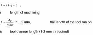
Figure 2-13. Determining the toolpath for longitudinal turning
Determining the toolpath for cross turning (Figure 2-14):
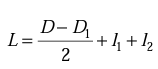
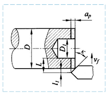
Figure 2-14. Determining the toolpath for cross turning
3. PLANING AND SLOTTING
Planing is a mode of cutting in which both the main and secondary movements of the cutting are mostly straight. In the process, chips with a constant cross-section ( f a A p ) are intermittently separated with a single-edged tool. Planing is used to machine planes, grooves and generally straight surfaces on long, narrow parts. Planing is displaced in many areas by higher productivity milling.
THERE ARE TWO BASIC VERSIONS OF PLANING:
- Cross-planing
- Long planing (usually for large pieces)
These differ in the distribution of main and secondary movements (Figure 3-1). When planing crosswise, the alternating straight main movement is performed by the tool, and the intermittent side movements are performed by the workpiece. In longitudinal planing, the main movement is performed by the workpiece, and the intermittent secondary movements are performed by the tool.
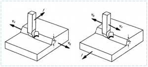
a) long planing b) cross-planing
Figure 3-1. basic versions of planing
Engraving can be considered as a vertical version of planing, in which the alternating main movement is performed by the tool and the secondary movements by the workpiece. It is most often used in the machining of internal surfaces. The tool must be run with a washer or a groove (Figure 3-2). It is most often used in the machining of internal surfaces.
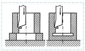
Figure 3-2. Engraving
Planing can be identified by turning (d=∞)), taking into account the conditions below the working stroke. Side movements pause during the main movement.
The design of the planer blade is similar to the design of the lathe blade, except that due to the greater protrusion and the dynamic load (the tool strikes the tool after each stroke), it is advisable to choose larger shank cross sections. Regarding the material of the tool, high-speed steel or sometimes a hard metal with high toughness is most often used.
The cutting data can be determined according to the correlations and guide values established during turning, with the value of the cutting speed having to be modified (reduced) due to the shocks during planing. The speed value obtained for turning must be multiplied by a modification factor Kmod = 0,75. The speed thus obtained shall not exceed 60 m / min.
Cutting forces and power are determined in the same way as for turning.