Lesson 1 – Turning
Read the textbook from the 1st page. You can find the textbook’s content on this link.
1.THEORY OF CUTTING
1.1 BASICS OF CHIP SEPARATION
CUTTING is a process of forming materials in which chips are mechanically separated from the workpiece using a wedge-shaped tool.
ELEMENTS AND COMPONENTS of the machining system:
- workpiece
- tool
- chip
- a machine that provides the energy and movement needed to interact with the workpiece and the tool
The model of the cutting process is a singleedged, straight-line tool is shown on the 1-1. illustration. 1-1.
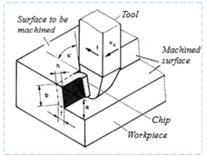
1.1 Figure Model of the cutting process
The cutting process can be divided into free and fixed cutting. The main features of free cutting are the nexts (1-2. illustration):
- the geometric kinetic conditions are the same at all points on the edge of the tool
- only one edge (main edge) of the tool is involved in cutting.
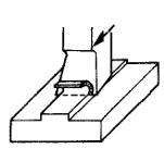
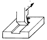
Figure 1-2. Free cutting. Figure 1-3. Bonded cutting.
In the case of knitted cutting, in addition to the main edge of the tool, the side edge or several edges also participate in the cutting (1-3. illustration). If we consider an arbitrarily short section of the chip width b, it can be considered as free cutting, and the edge can be considered as a series of elementary edges (1-4. illustration).
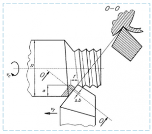
1-4.Figure Return of bonded cutting to free cutting on the example of longitudinal turning
When examining cutting theory issues, it is advisable to follow the principle of “simple to complex” gradation. Therefore, in most cases, the examination of the basic correlations is performed for free cutting.
1.2 OVERVIEW OF THE REQUIRED MOVEMENTS FOR CUTTING
Cutting requires the workpiece and tool to move relative to each other. This movement is a complex movement created by the movement system of the machine and consists of main and auxiliary movements.
The MAIN CUTTING MOTION is the movement in the direction of chip removal, which directly creates chip removal. The main drive of the machine establishes it by moving the workpiece or tool.
The CUTTING SIDE MOVEMENTS, when added to the main movement, ensure repeated or continuous layer separation. There can be movements in the feed direction or grip direction.
The secondary movement in the feed direction (feed) is the displacement that affects the chip thickness to be removed. In addition to the feedrate, in practice the feedrate f is used to characterize the feedrate movement, which is applied to a certain part of the cutting process, e.g. when turning, the movement of the tool during one turn of the workpiece (mm / rev), or during planing, the feed displacement per double stroke (mm / double stroke).
The side movement in the gripping direction usually determines the width of the chip, usually perpendicular to the feed and always intermittent. The magnitude of the displacement is called the depth of cut.
ADJUSTMENT AND AUXILIARY MOVEMENTS are required before starting the cutting process to bring the tool and workpiece into position. For example, before drilling, the tool must be moved above the hole.
1.1.1 CUTTING METHODS AND THEIR MOTION SYSTEMS
Each cutting mode has one main movement and one or more secondary movements. Depending on the type of main movement, the cutting modes can be divided into two groups (1-5, 1-6 illustration):
• rotary main motion cutting processes (esztergálás, fúrás, marás, köszörülés)
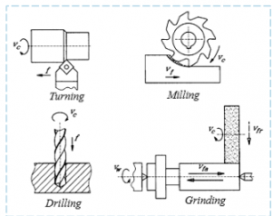
1-5. Figure Rotary main motion cutting processes.
• straight line main motion procedures (planing, chiselling, hollowing, sawing)
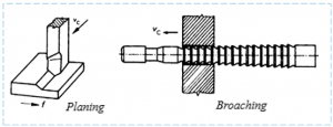
6 1-6. Figure Straight line main motion procedures.