Lesson 7- Mechanisms
2.3. Mechanisms
Kinematic analysis of structures is of great importance in mechanical engineering. Mechanisms can be divided into planar mechanisms and spatial mechanisms. In planar mechanisms, all of the relative motions of the rigid bodies are in one plane or in parallel planes. The mechanisms examined now have a single degree of freedom.
2.3.1. Scotch-Yoke mechanisms
This mechanism is used for converting rotary motion into a linear motion Fig. 2.3.1
Figure 2.3.1
The crank rotates at constant angular speed ω_0, defining the speed and acceleration of the slider.
The speed:
v_B=v_A sinφ=rω_0 sinω_0 t
The acceleration:
a_B=(dv_B)/dt=rω_0^2 cosω_0 t
The displacement:
x_B=∫_0^t▒〖v_B (t)dt=〗 rω_0 ∫_0^t▒〖sinω_0 tdt=r(1-cosω_0 t)〗
2.3.2. Slider crank mechanisms
This mechanism is composed of three important parts: the crank which is rotating, the slider and the connecting rod which joins the parts together.
Figure 2.3.2
The crank arm r shown in Fig. 2.3.2 rotates counterclockwise at ω_0. Find the velocity and acceleration of the slider.
2.3.3. Four-bar linkage mechanism
The four-bar linkage mechanism is shown in Fig. 2.3.3
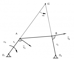
Figure 2.3.3
The mechanism has two rotating links which have fixed pivots. One of the levers would be input rotation, while the other would be output rotation. The two levers are connected by the coupler link l.
The crank rotates clockwise. Find the velocity of point B. Solve the problem graphically Fig. 2.3.4
v_A=r_1 ω_0
Velocity diagram
Figure 2.3.4