Lesson 2: Example of requirement: maximum wheel torque
Introduction:
- We will explore a use case surrounding passenger car powertrain development.
- Our focus: “Maximum Wheel Torque” requirement.
Setting the Scene:
- A vehicle manufacturer (OEM) is developing a Battery Electric Vehicle (BEV) for the European market.
- Drawing from prior experience with combustion vehicles, they have preliminary specifications and understand the needs of drivers, passengers, and legislations.
Initial Requirements:
- Car tire size: 205/55 R16.
- The vehicle will have front-wheel drive only.
- The car must achieve maximum torque and power of 100 kW momentarily at 90 km/h.
Deriving the Wheel Torque Requirement:
- Engineers determined that the powertrain must deliver a total torque of 1260 Nm.
- This translates to 630 Nm for each front wheel.
Calculating Motor Torque:
- To determine the torque needed from the e-motor, consider the system’s components.
- The OEM decides to repurpose the differential from its combustion vehicles.
- Using a stock reduction gear set, the complete reduction ratio from e-motor to wheel is established at 11.63.
- Therefore, the e-motor’s torque requirement can be deduced.
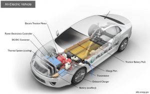
Figure Layout of a Battery Electric Vehicle (BEV)
Validation and Verification:
- E-Motor Testing:
- The e-motor is installed on a test bed, powered by an ideal electrical source, and linked to a dynamometer to regulate speed.
- The dynamometer sets the speed, and the motor’s torque is measured. For our case, assume it met the needed torque.
- Inverter Testing:
- The inverter’s role is to supply current to the e-motor.
- It’s tested under various conditions, using passive or active electrical loads.
- Active loads, like e-motor emulators, can mimic an e-motor’s realistic behavior.
- Successful tests confirm component-level requirement fulfillment.
Integration Process:
- The task now is to integrate the inverter and e-motor.
- This involves “teaching” the inverter to drive the e-motor under various conditions, such as:
- Varying driver inputs.
- Different driving scenarios.
- Changing environmental conditions.
- Interactions with other powertrain components.
- Integration ensures consistent performance within specified tolerances, leading to a uniform user experience and compliance with standards.
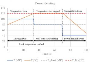
Figure Example of a simple derating strategy allowing the maximum possible power e.g. during an acceleration period
Integration Testing:
- Utilizing both measurements and simulation tools, the e-motor’s performance is characterized.
- Simulations, if mature and validated, can sometimes replace certain testing phases.
- The purpose: Cover all operation conditions, such as:
- Battery voltage ranges.
- Cooling scenarios.
- Thermal conditions.
- Successful tests result in an integrated system, with the inverter able to accurately drive the e-motor.
Advanced Integration:
- Progressing up the V model, the next step involves integrating the e-drive with the gearbox and differential.
- Modern powertrains are becoming increasingly integrated, making individual component validation challenging.
- Example: A shared cooling circuit for the gearbox and motor, necessitating special samples for component testing.
Conclusion:
- “Maximum Wheel Torque” is an essential requirement in BEV design, impacting various components.
- Ensuring each component meets its requirement and then successfully integrating them is pivotal to achieving the desired vehicle performance.