Lesson 8- DRAWING OF MECHANICAL PARTS (parts2)
5.4 WELDED JOINTS
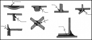
Welded joints(Figure 62) are among the most common and essential connections in the field of manufacturing and construction. These joints are formed by merging two metal surfaces using heat, and often with the addition of a filler material, to create a bond that’s typically stronger than the original materials. The process of welding provides a permanent union, ensuring structural integrity and continuity between the interconnected elements. With a variety of welding techniques available, each tailored to specific materials and applications, understanding the fundamentals and intricacies of welded joints is crucial for anyone involved in the design, fabrication, or inspection of metal assemblies.
Repair welding procedures are specialized techniques employed to rectify defects, damages, or wear in metal components. These methods involve the careful application of heat and filler material to restore the integrity of the original part without compromising its strength or functionality. Depending on the severity and type of defect, different welding techniques may be utilized. Such procedures are crucial in industries like aerospace, automotive, and heavy machinery, where the safety and longevity of components are paramount. Proper repair welding can extend the life of equipment, reduce replacement costs, and ensure continued safe operation.
5.4.1 Types of welding joints
The main types of welding joints are:
a) Edge Joint: The edges of two pieces are set side by side and then welded.
b) Corner Joint: Two pieces are joined at their ends, forming a corner.
c) Lap Joint: Two pieces are overlapped and then welded where they overlap
d) V-Groove, Butt Joint: Two pieces are joined end to end.
e) Double V-Groove joint: It is a specialized type of welding joint used for joining thicker plates or workpieces. As its name suggests, this joint utilizes two V-shaped grooves on both sides of the workpieces.
f) T-Joint (or Tee Joint): One piece is joined to the middle of another piece, forming a “T” shape.
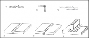
62. Figure Types of welding joints
Each of these joints can be used in various applications depending on the requirements of the structure and the materials being welded.
5.4.2 WELDING SYMBOLS
While some welding symbols(Figure 63, 64) may initially appear complex, they become straightforward when dissected. These symbols represent side views of the pre-weld joint, much like viewing a cross-section. Each symbol comes with a detailed explanation, paired with its weld profile.
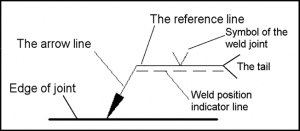
63. Figure The base platform
This symbol serves as a basic framework to showcase the features and related details of your welds. It consists of three components:
• The arrow line: directs attention to the weld’s general location.
• The reference line: acts as the space where the details about the weld’s type and exact location are presented.
• The weld position indicator line: The weld position indicator line in the base platform specifies the position in which the weld is to be performed.
• The tail: provides space for additional information unrelated to the primary specifics, such as welding standards, the type of materials, and the necessary welding procedure.
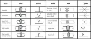
64. Figure The symbols of the weld joints
5.4.3 SUPPLEMENTARY WELDING SYMBOLS
These markers(Figure 65) complement the basic symbols to specify the required weld type. They encompass the weld’s attributes, instructions on where and how to execute it, and the necessary finishing details.
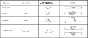
65. Figure Supplementary welding symbols
• Flush finish: This welding symbol indicates that the weld must be machined or ground to align flush with the surface of the remaining plate. The symbol is represented by a straight line, illustrating the appearance of the final surface.
• Convex: The convex finish of a weld bulges outward, resembling a balloon extending away from the weld, as depicted by its symbol.
• Concave: The concave symbol curves in a direction opposite to that of the convex, indicating that the weld should have an inward curvature, similar to the inner surface of a bowl. This finish is commonly associated with fillet welds.7
• Racking weld: This refers to the requirement for a preliminary weld at the base of a weld preparation, such as a V or U, before completing the entire weld. This initial weld provides a foundation for the complete weld, preventing it from burning through due to excessive heat when only a slim portion of the material is left. Its symbol, represented by a curved line, is positioned either below or above the primary welding symbol, based on which side of the reference line the main symbol is located.
5.5 SOLDERED AND BRAZED JOINTS
Soldering and brazing are both techniques used to join metals without melting the base metals themselves. Soldering involves the use of fillers, known as solders, that melt at temperatures below 450°C (842°F). Due to its relatively low melting point, soldering is primarily used for delicate tasks like joining electrical components. In contrast, brazing uses filler metals, known as brazing rods, that melt at temperatures above 450°C but below the melting point of the base metals. Brazing provides a stronger bond than soldering and is often used in plumbing, metalwork, and in the construction of more robust structures. Both methods, when executed correctly, create a seamless bond that can be as strong as the metals being joined.
Before soldering or brazing, surfaces require thorough preparation to ensure a strong and effective bond. First, the areas to be joined must be cleaned to remove any oxidation, grease, dirt, or other contaminants. This can be done using solvents, wire brushes, or abrasives. Applying a flux before soldering or brazing is also crucial. Flux facilitates the flow of the filler material and helps prevent the formation of oxides during the heating process.
66. Figure Soldered joints
The strength of a soldered or brazed joint depends on various factors including the materials used, the quality of the preparation, and the techniques applied. Generally, a brazed joint offers a stronger bond compared to a soldered joint due to the higher temperatures involved, which allow for better penetration and flow of the filler material. However, both soldered and brazed joints, when executed correctly, can provide connections that are robust and reliable for their intended applications.
5.6 GLUED JOINTS
In the field of mechanical engineering, adhesive bonding has become an integral method for joining components. This technique offers several advantages over traditional joining methods such as welding, bolting, or riveting. Adhesive bonded joints distribute stress more evenly across the bonding surface, reducing localized stress concentrations. This can lead to lighter, more streamlined designs as there’s no need for additional fasteners or overlapping material. Additionally, adhesive bonding can join dissimilar materials, including metals, plastics, and composites, which might be incompatible with other methods. The process also provides excellent resistance to fatigue, vibration, and environmental factors. However, surface preparation and the choice of the right adhesive are critical to achieving a strong and durable bond.
Before adhesive bonding, it’s essential to thoroughly prepare the surfaces to ensure optimal adhesion and the long-term durability of the bond.
Steps for surface preparation:
• Cleaning: Start by removing any loose particles, dust, or dirt from the surface. This can be done using a soft brush or compressed air.
• Degreasing: Remove any oils, greases, or contaminants from the surface using appropriate solvents or degreasing agents. After applying the solvent, wipe the surface with a clean, lint-free cloth or rinse with clean water, depending on the solvent’s instructions.
• Abrading: For some materials, lightly abrading the surface can enhance adhesive bonding. Sanding with fine-grit sandpaper or using abrasive pads can create micro-roughness, increasing the surface area for the adhesive to grip.
• Chemical Treatments: Certain materials, especially metals and some plastics, may benefit from chemical treatments like etching or priming, which can increase surface energy and improve adhesive wettability.
• Rinsing: After chemical treatments, it’s crucial to rinse the surface with distilled or deionized water to remove any residues.
• Drying: Ensure the surface is completely dry before applying the adhesive. This can be done using clean compressed air, heat guns, or simply letting it air dry, depending on the material and the specific application.
• Immediate Bonding: After preparation, it’s advisable to proceed with the bonding process as soon as possible to prevent the surface from becoming re-contaminated or oxidizing.
In the context of adhesive bonding, “delamination” refers to the separation or splitting of layers within bonded assemblies(Figure 67). When subjected to bending stresses, ancillary tensile stresses can arise, especially near the edges of the bonded material. These stresses can exceed the adhesive’s capacity to maintain cohesion, leading to a peeling or separation at the edges. Essentially, the bonded layers start to peel away from each other, compromising the integrity of the bond. Delamination can be a significant concern, as it weakens the overall structure and can lead to complete bond failure if not addressed. Ensuring proper surface preparation, using the appropriate adhesive, and considering the mechanical loads and environmental conditions the bond will be subjected to are crucial to mitigate the risk of delamination.
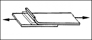
67. Figure Delamination of glued bonding