Lesson 7- DRAWING OF MECHANICAL PARTS (parts1)
The detailed graphical representation of machinery components is an important aspect of engineering practice. This encompasses the precise dimensions, tolerances, materials, and other specific details that are essential for manufacturing, assembly, and maintenance. These drawings serve as a blueprint for engineers, technicians, and manufacturers to ensure that parts are produced to exact specifications. They play a crucial role in industries like automotive, aerospace, and manufacturing, ensuring consistency, functionality, and safety in products. Proper documentation of these drawings is imperative for quality control, revisions, and future reference.
5.1 FASTENERS AND THREADED JOINTS
The elements of threaded joints are the best known fastener components. The bolts and screws are used in any device. If you want to make a connection between parts the threaded joints give you a reliable option. These connections are removable without damage of parts.
By converting rotational movement to linear motion, they allow for precise adjustments and positioning in mechanisms. This function is particularly vital in applications like lead screws in machinery, where minute adjustments can drastically affect performance. Additionally, threads play an integral role in fastening, ensuring components remain securely joined. Their design and pitch can be tailored to specific applications, making them versatile tools in the realm of mechanical engineering.
5.1.1 DIMENSIONS OF THREADS
Figure 52 shows a “V” shape thread whick is perfect for describing the main information of threads. The thread is basically a slope which is rolled up on a cylinder surface. The length of the slope os equal to the circumference of the cylinder and the height is equal to the pitch. A rotation causes the screw nut to move up the slope of the cylinder(thread) by as many milimetres as the height of the slope(pitch).
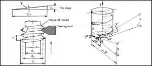
52. Figure Dimensions of thread
The main dimensions are standardised:
d- nominal or major diameter
P- pitch
d1- minor diameter
d2- pitch diameter
Ψ- angle of the pitch
5.1.2 TYPES OF THREADS
- Metric screw: The best-known type of “V” shape thread. Dimensions are in milimeters. The all of dimensions are required by standard.
- Withworth screw: The next type of “V” shape tread. Dimension are in inchs. Usually it is used for pipes and fittings.
- Knuckle thread: The edges of thread shapes are rounded. In this way the screw has smaller amount of strees in the material.
- Square thread: Used for moving spindles. Rarely used nowdays.
- Acme thread: Most commonly uses power screw. It is a trapezoidal thread form. This construction can take more force and stress.
- Buttress thread: This type of thread can withstand high one-way forces well.
- Wood screw thread: It is used for timber.
5.1.3 TYPES OF SCREWS
Screws are made in many lengths and with many head designs.
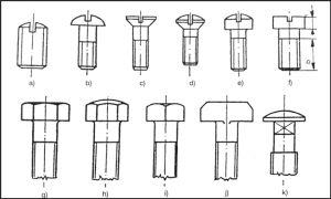
54. Figure Types of threads
a) Worm screw
b) Screw with hemispherical head
c) Flat(Slotted) head
d) Oval head
e) Filister head
f) Cheese head
g) Hexagon head
h) Button hexagon head
i) Squaere head
j) T-head
k) Round head square neck
Most of the screws are right-handed. They do not need any marking. If the screws are left-handed extra sign is neccessary. These are turned signs on the external surfaces of the bolts and heads of screws.
5.2 TAPER KEYS
A key is a mechanical part situated at the junction between a shaft and the hub of an element that conveys power, serving to transfer torque. This key can be removed to simplify the assembly and disassembly of the shaft mechanism. It fits into a longitudinal groove crafted in the shaft, known as a keyseat. In many cases we fix pulleys and hubs with keys. The most of taper keys have 1% taper . We do not draw the true shape of taper key. We draw a square key and write to close the taper of the key.
The taper key has a symbol which reminds a slope. After the sign there is the gradient of the slope(taper) which is shown with a percentage(1:100).
The gib head key, as depicted in Figure 59, features a tapered design within the hub, mirroring the plain taper key’s shape. However, its elongated head allows for the key’s removal from the same side it was inserted. This feature proves especially beneficial when the other end isn’t reachable for key extraction. A great advantage of the gibhead key is that it can be removed with a suitable tool by clinging to its protruding part.
The disadvantages of taper keys:
- They require a lot of force to dismantle,
- The loose fit causes the hub to fit loosely on the shaft, so after assembly, the geometry and center of rotation may not coincide,
- The location of the taper key connection is not exact,
- The stress from the force can cause deformation,
- The taper key moves the hub out of its perpendicular position.
5.3 SQUARE AND RECTANGULAR PARALLEL KEYS
For shafts with diameters ranging up to 8-50 mm, the square key is typically used, depicted in Figure 60. The rectangular key is advised for more extensive shafts and can also be used for smaller shafts when a reduced height is acceptable. Both the square and rectangular keys are known as parallel keys due to the parallel nature of their top and bottom, as well as their sides.
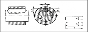
60. Figure Square key joint desgn and shape
The design of the keyseats in both the shaft and the hub ensures that half of the key’s height is supported by the side of the shaft keyseat, while the remaining half is supported by the side of the hub keyseat. The resulting design is depicted in Figure 60. Typically, keyseats in shafts are crafted using either an end mill or a circular milling cutter, resulting in the profile keyseat or sled runner keyseat, respectively.
When there’s a preference for light loading and straightforward assembly or disassembly, one might think about using the Woodruff key. The key remains in place within the shaft’s circular groove while the corresponding part is slid onto it. Stress evaluation for this key follows the approach used for parallel keys but factors in the unique shape of the Woodruff key. The dimensions for numerous standard Woodruff keys and their respective keyseats can be found in the ISO and ANSI standards.