Lesson 6 – TECHNICAL DRAWING (part2)
4.4 THE RULES OF GIVING DIMENSIONS
Our parts must be sized on our technical drawings so that they can be manufactured. The basic principle is that we do not take dimensions from drawings. Dimensions are given in mm without any indication of the unit of measurement.
4.4.1 THE ELEMENTS OF SIZE SPECIFICATION
• dimension line,
• scale reference line,
• indicator line,
• dimension line delimiter,
• end point and starting point of dimension line,
• dimension number.
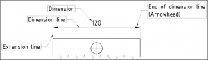
44. Figure Elements of dimensions
The DIMENSION LINE is given parallel to the direction of the dimension, by a straight line or a circular arc, with a thin solid line. No other lines shall cross and dimension lines shall be at least 6-8 mm apart and at least 10 mm from contour lines. Size lines for dimensions should be broken only when necessary.
Draw the SCALING REFERENCE LINES with a thin solid line so that it extends beyond the dimension line boundary by at least 2 mm. The dimension lines do not always enclose 90° to the dimension line. You can draw the scale lines at an angle, but they must still be parallel to each other.
Information on the characteristics can also be given with a INDICATOR LINE. The line can be joined:
- with a point, if you point inside the contours of the object,
- an arrowhead, if you point to the contour of the object,
- without end (without point and line), if you point to the dimension line.
The end of a scale line is terminated by a SCALING LIMIT, which can be:
- the dimension arrow, with an opening angle of 15°, with a minimum length of 2,5 mm, not crossed by any line other than the line of the sections,
- the oblique line is used when the size itself is small and space is limited, the size arrow is drawn at an angle of 45° with an oblique line at least 3,5 mm long,
- The dimension point may be empty or filled and is also used when space is limited.
- The empty circle is also used to indicate the starting point when scaling from a common base. A minimum circle of 3 mm (blank point) is used to mark the point.
When entering the DIMENSIONS, please prefer writing in the perpendicular (vertical) direction. Letters appearing in dimensions should be written obliquely.
4.4.2 Special markings for dimensions
Dimension numbers can be provided with special markings to give additional information about the dimension.
The underline below the scale number symbolises that the representation is not to scale. It is not used in principle for scaling parts in foregrounds and interrupted plots (e.g. long axes).
Dimensions that are drawn around (placed in a bubble) are given special attention by the customer. Usually we mark them when we work with several suppliers in a production company. On receipt, the dimensions marked in this way will be checked (100%) to make sure that they are correct.
Auxiliary dimensions are put in brackets. These dimensions are not required for production and are not subject to general tolerances. They are only intended to facilitate interpretation by the reader of the drawing.
The theoretical dimensions, which are the geometrically desirable location of a point, line or surface, are given by framed dimensions.
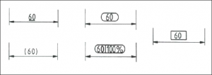
46. Figure Special marks of dimensions
4.4.3 Entering dimensions
There are two ways to enter the dimensions:
- The dimensions are placed in the middle of the dimension line, legible from left to right or bottom to top. If they do not fit on the scale line, they may be placed at the extended end of the scale line.
- Horizontal sizes are placed in the middle of the scale line, and non-horizontal sizes are placed in the middle, interrupting the scale line. The dimensions read from left to right.
4.3.4 SUPPLEMENTARY SYMBOLS
The dimensions given are in mm, if different, an additional symbol must be placed after the dimension number, e.g.: 10°, ½”, 15 m . The radius R, diameter symbol, etc. is placed before the dimension number. In the case of a square, the size number always refers to the span. When indicating radius and diameter, the additional drawing symbols must always be indicated (even if the projection shows the whole circle).
Instead of the square (□) sign, it is also allowed to use the inscription e.g.: 25×25. When indicating the arc length of circular arcs, an arc symbol (ᵔ) must be placed above the size number. If the flattened flat surface on the projection is visible from the front, a cross on the surface, when two diagonals are drawn in, indicates that a flattening is visible. This is necessary because in side projection, a cylinder and a brick body show the same image.
To define spherical areas, use the sphere radius (sign:SR) and sphere diameter (sign:SØ).
4.4.5 STRUCTURE OF THE MEASUREMENT NETWORK
To show the dimensions of the part, place the dimensions in order.
THE MECHANICAL DRAWING SHOWS ONLY THE NECESSERY AND SUFFICIENT DIMENSIONS. DO NOT USE MORE DIMENSIONS WHAT YOU NEED DESCRIBE THE COMPONENT!
The design of the measurement network must take into account the production and operation of the component. Consequently, each surface may have different properties. It may be necessary to specify the position of certain surfaces relative to each other in order to determine the position of connecting elements.
Dimensions should preferably be given in such a way that they can be measured on the workpiece as it is mounted on the machine tool. Take account of the manufacturing process. Try to design the part to minimise the number of times it has to be clamped in the machine tool during machining, as each clamping can introduce inaccuracies into the workpiece.
The dimensioning in Figure 49 is adapted to the application of the tool, the machine tool and the clamping device. In the figure on the left, the spindle hook was formed with a finger milling machine, and in the figure on the right, a wedge hook was formed with a chisel in a brain. The dimensions in the drawing are given so that the manufactured size can be easily measured.