Lesson 5 – TECHNICAL DRAWING (part1)
The representations described so far have shown the construction of bodies by superimposing or substituting certain building blocks. The external and internal geometry of the object can be represented well with the knowledge we have acquired so far, but even so the drawing does not provide enough information about the part for manufacturing. To be able to make a machine drawing from a diagram, you need to know the rules of sectional representation, dimensioning, symbolic representation, standard notation.
4.1 THE PURPOSE OF MECHANICAL DRAWING
In industry, they can make different objects and parts from drawings. These drawings are called TECHNICAL DRAWINGS. In technical drawings we record information about the shape, dimensions, etc. of objects according to the rules of technical representation. We also record administrative data (date, designer’s name, editor’s name, signatures, validity, version number).
In engineering, we often make SKETCHES, which are usually made freehand, not necessarily true to scale and proportion. Such sketches are usually temporary drawings, made during production in response to a problem that arises. We may supplement a drawing of a prototype. In agreement with the technology and design, any modifications must be recorded immediately in the valid production documentation.
A special type of technical drawing is a DRAWING, used in the field of engineering. A machine drawing carries several pieces of information that refer to the manufacture and purpose of the part. It contains the necessary information about the manufacturing technology, material quality, machining accuracy, surface treatment, coating, moving part positions, etc. in the form of inscriptions, instructions, drawings.
Type of technical drawings:
Machine drawings can be further classified according to the purpose for which they are intended and the type of information they are intended to convey. The following list also reflects the steps in the implementation of a product, from the drawing board to operation.
- Conceptual drawings (sketches)
- Flow chart
- Roadmap
- Wiring diagram
- Proposal drawing
- Calculation sketch
- Preliminary design
- Editorial drawings
- Assembly drawing
- Dimensioned assembly drawing
- Production drawings
- Component drawing
- Workshop drawing
- Establishment drawings
- Layout drawing
- Machine foundation drawing
- Operational drawings
- Maintenance drawing
- Handling drawing
The system of representation and notation is standardised to ensure that the interpretation of drawings is clear around the world. In many cases, the design office and the manufacturing company are not even on the same site and the designer and the technologist do not even interact personally. A component may have several suppliers and all of them must provide the same quality of product. It is also common for a component to go through several specialised factories during its production. This shows how important it is to be able to interpret a machine drawing we produce, regardless of the language.
4.2 STANDARDS
Standardisation is the result of common agreements that define rules, standardise methods, machine components and systematise our technical knowledge in a particular field.
A standard is a technical specification that fixes:
- parameters
- properties
- specifications
- requirements
- test and inspection methods
It can be subject to standardisation:
- product, produce, installation, equipment
- concepts, definitions, designations, symbols, methods of representation, measurement and calculation used in technical and economic activities
- safety at work, technical requirements for the protection of life, health, physical safety and the environment
- organisational, administrative and documentation methods and tools
- technical requirements for services
- procedures and methods for quality assessment and certification
The level of standards:
- International standards- ISO (International Standard Organisation)
- – Regional standards
- EN(European Standard)European standard; Issuing body: CEN(Comité européen de normalisation)
- National standards
- MSZ(Hungarian Standard)
- DIN(Deutsches Institut für Normung)- German National Standard
- ANSI(American National Standards Institute)- USA National Standard
- GOST(GOsudarstvennyy STandart)- Russian National Standard
- – Company standards
4.3 CROSS-SECTIONS IN MACHINE DRAWING
The representation of spatial objects in the plane is well captured by the geometry, but the jagged lines of internal edges and articulations (holes, cavities, grooves) not visible in the view are difficult to interpret and often confusing. With the help of the sectional representation, however, some of the pithy shapes and shaped surfaces can be clearly shown.
4.3.1 CONSTRUCTING SECTIONAL VIEWS
With an intersection plane, we cut our part in imagination and, removing the part in front of the intersection plane (closer to us), we represent the part of the object(Figure 33) behind the intersection plane according to the rules of projection. The intersected parts of the material are called sections and are marked (hatched) with line drawing. It is very important that the sectional view includes a plan view of the parts of the material beyond the section.
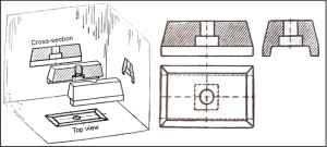
33. Figure Rules of prjection represented on a part
The line direction of the section, section should be 45° to the:
- with a contour line or,
- the axis of symmetry,
- if a curved element is drawn, with the chord of the curve.
Within a part, the sections should be aligned in the same size and orientation. On assembly drawings, the parts in contact shall have different hatching. The direction and spacing of the different hatching may be different. The hatching is usually indicated by lines with a 45° slope, but this may be deviated from if the material quality is to be illustrated in the sectional view. Simple line scribing usually indicates a metallic part. Figure 35 shows the other section patterns that can be used, depending on the type of material. This used to be more important. Today, because of the variety of materials, the standard material grade is given in the bill of materials anyway. To aid interpretation, it is useful to use at least these few notations on our drawings.
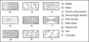
35. Figure Section patterns