Lesson 4 – GEOMETRY OF SPACE (part2)
3.3 EXAMPLES OF SURFACES IN TECHNICAL PRACTICE
In our studies we have made our drawing in the plane of our drawing paper, using a ruler and a compass. In space we cannot work with these tools, so we have to make our spatial geometry constructions in our heads, in our minds – and then we can record them on a drawing paper using the rules of descriptive geometry.
Firstly we have to define the rules of spatial drawings making. We need to introduce some new concepts.
3.3.1 DRAWING PLANES
A PLANE is considered to be constructed if the spatial elements which clearly define the position of the plane in space have been found.
We can draw a plane:
• with three points
• on a straight line and an external point
• an intersecting pair of straight lines
• a pair of parallel lines
In the case of two intersecting planes are given, their intersection lines are given thus we can determine the intersection of two planes in space. Once we have defined a plane in space, we can do all the drawings in this plane what we do in descriptive geometry.
3.3.2 DRAWING OBJECTS WITH FLAT LINE SHAPES
The FLAT LINE SHAPES are prsim, cube, pyramid. The prism or the cube can laying on their any planes but the pyramid just can only stand on its base plate. The standing object has a vertical axis and its ending plane is horizontal. The vertical edges look like point on the base plane.
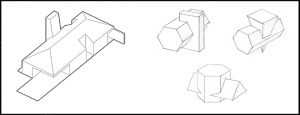
29. Figure Objects build from flat surfaces
Various engineering components can be designed using the geometric forms of cubes, rectangular prisms (or cuboids), and pyramids(See Figure 29):
- Cubes: Being equal in all dimensions, cubes can be used in certain modular designs or components that require symmetry. Examples include:
- Square shaft ends
- Structural blocks for assemblies or constructions.
- Calibration blocks in metrology.
- Certain types of weights or counterbalances.
- Rectangular Prisms (Cuboids): With their three distinct dimensions, these are one of the most common shapes in mechanical design. Components or structures derived from this shape include:
- Casings or enclosures for electronics or machinery.
- Shipping containers or storage boxes.
- Battery cells in certain configurations.
- Base structures for platforms or machinery.
- Pyramids: In buildings and building services engineering, pyramid or conical shapes can be observed in various applications due to their distinct structural and functional advantages:
- Roofs: Pyramid-shaped roofs, often seen in traditional or historic architecture, can aid in water runoff, offer a distinctive aesthetic, and provide additional space beneath.
- Ventilation and Exhaust: Conical ducts or vents, used in HVAC systems, help in regulating and directing airflow. Their tapering design can increase or decrease the velocity of air or other fluids, depending on the application.
- Light Fixtures: Pyramid or conical shapes in light fixtures can help direct light in a particular direction, providing focused illumination or creating specific ambient effects.
- Acoustics: In some spaces, conical structures or surfaces can be implemented to manage sound reflection or absorption, optimizing the acoustic properties of a room.
3.3.3 DRAWING OBJECTS WITH SOLIDS OF ROTATION
The SOLIDS OF ROTATION are cylinder, cone, sphere and the circumferential ring. Combinations of these can produce many of the shapes used in engineering practice. Examples include the junction of tubes of different diameters, cylindrical and conical sheet metal parts or a solid shafts with cylindrical bores.
Various components can be designed with cylindrical, conical, and spherical surfaces.
- Cylindrical surfaces are commonly used in parts such as shafts, rods, barrels, rollers, and sleeves. They provide a uniform cross-section and are typically utilized for rotating elements or parts that need to slide within other components.
- Conical surfaces, having a tapering shape, can be found in parts such as nozzle tips, tapered bearings, and certain types of gears. Their design often serves specific functions, like guiding or centering components, or enabling tighter fits between parts. The tapering design offers unique advantages in various components. Some applications include:
- Conical filters, funneling substances through a decreasing cross-sectional area.
- Certain types of nozzle or vent designs, directing flow in a particular direction.
- Spikes or pointed feet for machinery or equipment to ensure grip or stability on a surface.
- Spherical surfaces are seen in components like ball bearings, ball joints, and certain types of lens. They provide omnidirectional movement or rotation, making them ideal for parts that require unrestricted movement in multiple directions.
Each of these geometric designs offers unique advantages depending on the application and the specific requirements of the component in the larger mechanical system. The Figure 30 below shows a shaft designed as a combination of cylinders and cones.
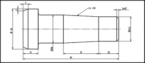
30. Figure Shaft made up of cylinders and cones
3.3.4 COMPLEX SHAPES OF PARTS
In mechanical engineering, most surfaces are born from a combination of flat planes and revolution bodies(Figure 31,32). The design and development of components and structures often involve a harmonious blend of flat planes and bodies of revolution. While flat planes provide stability, ease of manufacturing, and simplicity in assembly, bodies of revolution, generated by rotating a curve about an axis, offer smooth transitions, efficient flow dynamics, and uniform stress distribution. Cylinders, cones, and spheres, all examples of revolution bodies, are frequently combined with flat surfaces to create parts like shafts with flanges, conical nozzles with mounting bases, or spherical tanks with planar supports.
The melding of these two fundamental geometries allows engineers to tailor designs to specific functional requirements while optimizing manufacturing processes. This synergy between flat planes and curved surfaces is a testament to the adaptive and innovative nature of mechanical engineering, ensuring both functional efficiency and design elegance.
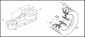
31. Figure Complex parts
In the differential mechnaism shown in Figure 32, the components formed using complex surfaces can be clearly observed. When looking at the axes of the components, parallel, intersecting or skew lines(axes of the parts) are clearly visible. The axes of the parts are marked with a dotted line.
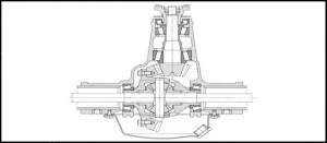
32. Figure Differential mechanism