Lesson 3 – GEOMETRY OF SPACE (part1)
Descriptive geometry is concerned with the representation of spatial shapes in a plane according to a defined method. Knowledge of the technique of representation is of paramount importance in engineering practice. When designing components, we often use 3D modelling CAD software that knows the rules of projection. We will not be able to design, optimise for production and produce a understandable view of complex shapes if we do not know the basic principles of technical drawing and ortographic projection.
3.1 Basic knowledge of Elements of space
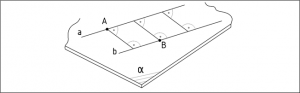
In order to represent solids in Euclidean space, it is essential to understand the concepts of point, line and plane as the building blocks of space. The point is the simplest element without extension, which can be defined as the intersection of two lines on a plane. Several points can form geometrical elements as lines, curves, planes. The positions of the points are marked by a cross or a circle and are denoted by capital letters(A,B,…) or Arabic numbers (1,2,…). To denote the line, we use small letters(a,b,…) and the planes are denoted by Greek letters(α,β,…). See the signs in Figure 9.

9. Figure Drawing and marking point, line and plane
The following fundamental theorems about the properties of spatial elements are accepted without proof:
1.Only one line can be drawn through two points.
2.A single plane can be laid across three points if they are not on a straight line.
3.If 2 points of a line lie on a plane, then all points of the line lie on that plane.
Thus, a line is perfectly defined by two points, and a plane is perfectly defined by three points not lying on a line. For example: ‘AB’ is a line or ‘ABC’ is a plane. Also fundamental element is the segment, which is defined by the distance between two points on a line. So the distance between points ‘A’ and ‘B’ is the distance of ‘AB’ or ‘AB’ segment. Using the sign of a line, we can also use a small letter to denote the segment, e.g. segment ‘a’.
To continue the list of basic items:
4. Two lines are parallel if they lie in the same plane and do not intersect (Figure 10).
10. Figure Paralel lines
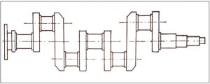
Parallel lines can be observed in many places on machine parts. A good example of this is the crankshaft of a motor vehicle, where parallel and coincident lines can be observed at the bearing seats (Figure 11).

11. Figure Vechicle crankshaft
5. An intersection is defined as two lines that have a single point in common. A plane can be laid on two intersecting lines (Figure 12). The angle subtended by the intersecting lines has no effect on the position of the plane laid on them.

12. Figure Intersecting lines
3.2 ANGLE AND DISTANCE OF ELEMENTS
3.2.1 ANGLES
An angle is formed by two straight lines with the same starting point. The vertex of an angle is the origin and the position of the lines determines the size of the angle.(Figure 20a).
When two lines intersect, four angles are formed, where the two opposite angles are equal, and the smaller of the two (the acute angle) is called the angle of the lines. In Figure 20b, the angle of the lines ‘a’ and ‘b’ is angle α.
If the adjacent angles around the intersection of the lines (Figure 20c) are equal, the two lines are called perpendicular. Their angle is 90°.
To determine the angle of skew lines (Figure 20d), the two lines are shifted to any point in space (parallel to themselves). The angle of the shifted lines is equal to the angle of skew lines.
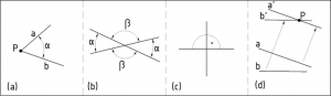
20. Figure Angles of the intersected lines and skew lines
3.2.2 DISTANCES
The distance between two points is called the straight line segment between them, or its length.
As stated earlier, a point and a line define a plane. In this plane, the length of a perpendicular segment from the point to the line gives the distance from the point ‘P’ to the line ‘a'(Figure 25).
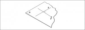
25. Figure Distance between a line and a point
The distance of a point from a plane is the length of the perpendicular segment from the point to the plane. As illustrated in the example in Figure 26, the segment ‘PD’ between the point ‘P’ and its intersection with the normal plane ‘D’.
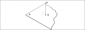
26. Figure Distance of a point from a plane
The distance of two parallel lines is equal to the distance of any point on one line from the other line (Figure 27).
27. Figure Distance between parallel lines