Lesson 2 – THE RULES OF ORTOGRAPHIC PROJECTIONS
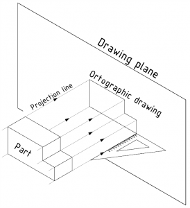
The axonometric representations discussed in the previous chapter provide illustrative “pictorial” representations. The editing is more complex, which is no longer a problem with CAD systems. However, specifying dimensions, tolerances, surface properties, technological symbols would be difficult in axonometry and would give an unclear picture. This would make it much more difficult to read the drawings and therefore also to produce them. For this reason, the drawings are made using ORToGRAPHIC PROJECTIONs, which is carried out by projection to a plane. After projection, the picture of the object on the plane is the PROJECTION. The rules for projection methods are described in the standard EN ISO 5456.
5. Figure Method of projection
2.1 Vertical projection
In technical practice, the projection is mainly perpendicular, because in most cases there is no angle and no distortion on the projection (Figure 5). The projection beams are perpendicular to the image plane and parallel to each other. The dimensions of the projection are the same as the dimensions of the object. The resulting projection is called a perpendicular projection. Different objects can have the same projection, so several projections are drawn from one part. Draw more than three projections of an object only if absolutely necessary. The same information given more than once can be confusing to interpret.
French engineer Garpard Monge (1764-1818), “the father of descriptive geometry”, created the method of projection, which has been used unchanged ever since. When we draw a part in the 3D modelling environment of CAD software, we see an image generated according to the laws of projection on the computer’s flat screen(Figure 7).
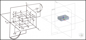
7. Figure Monge plane system
The picture plane system consists of at least two perpendicular planes. The intersection points of the planes build the axes of the picture planes. The projections of the points are identified by the capital letters of the alphabet and are given an index indicating which plane they lie on. The index can be a comma or a number. If you have few projections on the drawing page, you use a comma as an index, but if you have many projections, you use Arabic numbers to indicate the letter of the points.
2.2 Standard projections
Imagine that the object is placed in a square box (Figure 8). By projecting rays perpendicular to the object onto the faces of the square, a projection of the object is made on each of the six faces of the box. By cutting the edges of the box, the sheets can be laid out in a plane, so that 6 projections are seen in a single plane. The 6 views are called front view, top view, left view, etc., based on their position relative to the object, as illustrated in Figure 8. The main view of the object is the front view, which carries the most information about the object. The other views are arranged around the front view. Always draw as many views of an object as are sufficient and necessary to identify, scale and construct the object.
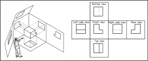
8. Figure Orthographic projection and European Standard Views
In the case of graphical representation, the axes of the image planes, image planes, axes of transformations are not indicated. When designing, representational geometric constructions can be very important, but their axes and construction lines are not indicated on component drawings and assembly drawings because it would be confusing.